Bill of Materials (BOM)
Carefully read the specifications to order the correct component.
Hardware
| Component | Qty | Specification | Where to Buy |
|---|---|---|---|
| Hex socket screw set | 1 set | M3 / M4 / M5 assortment, stainless steel | AliExpress · Amazon |
| Countersunk screws | 2 pcs | M3 × 5mm, flat head, stainless | AliExpress · Amazon |
| Hexagon Socket Allen screw | 2 pcs | M4 5mm It’s often available as a spare part for printers (check before buying—you may already have them). It’s used to secure the heat break as well as pulleys on shafts. | AliExpress |
| Bearing | 5 pcs | 4 × 12 × 4 mm 604ZZ | AliExpress |
| Spring | 1 pc | 0.6mm wire, 40mm length, 6mm OD | AliExpress |
| Aluminum tube | 1 pc | 35mm OD × 32mm ID × 700mm length Can substitute fiberglass, carbon fiber, PVC, or steel (heavier). Usually cheaper at local hardware stores. | Amazon |
Battery Compartment
| Component | Qty | Specification | Where to Buy |
|---|---|---|---|
| AWG wire | 5 m | 26 AWG wire (black + white) | AliExpress |
| Battery Shrapnel | 2 pcs | Battery contacts | AliExpress |
| Battery Holder | 3 | Battery Holder for 3 x 1.5V AAA | AliExpress |
ESP 32 board setup components
| ESP32-S3-WROOM-1 N16R8 | aliexpress |
| PAM8403 | aliexpress |
| PCM5102A | aliexpress |
| 0.91 Inch OLED Module | aliexpress |
| mini560 5V | aliexpress |
| TB6612FNG | aliexpress |
| 2k ohm and 10k ohm resistor | aliexpress |
| A103 10K Duplex Dial Wheel Gear Potentiometer | aliexpress |
Printing
All parts are designed to print without supports — where supports are needed, they are already integrated into the model and will need to be removed during assembly (more on this in the Assembly section).
A ready-to-print Bambu Lab project file is provided with all parts pre-arranged on build plates. Each plate is named after the assembly it belongs to: Handle, Blade, Body, etc. The parts are already oriented in the correct printing position — just slice and print.
Print Settings
Minimum settings for all parts: 2 walls, 10% infill.
Exception — Chainax_Body part: print with minimum 3 walls and 30% infill. This part bears higher mechanical loads from the motor and gearbox.
Material
Any common filament will work: PLA, PETG, or ABS. There is no significant difference in performance for this project — choose whatever you are most comfortable printing with.
You’ll need at least 2 kg of filament for printing; it’s better to take extra in case of defects.
Where more than one copy of a part is needed, the quantity is indicated in the file name.
⚠ CHAIN ELEMENT COUNT
Demon Axe style: 37 chain elements
Viking Axe style: 38 chain elements
Prepare these parts before assembly.
For a better understanding of the next three steps of soldering the wires, I will provide the final wiring diagram of the entire electronics setup.
Prepare these parts before assembly.
Motor wiring
You will need approximately 40 cm of wire for the motor connection. Solder the black wire to the motor terminal marked with a red dot — this ensures correct polarity. If the chain rotates in the wrong direction after assembly, simply swap the two wires either at the motor terminals or at the FR120N board.
Battery Compartment Assembly
The battery compartment holds nine 9 AAA batteries in series (9-13.5V). All parts for this section should already be 3D-printed. You will need a soldering iron, 22AWG dual wire (red + black), heat shrink tubing, on/off switch and a hot glue gun (optional).
To enlarge the images in the instructions, simply click on them.
01 Install the positive contact
Take the positive (+) battery contact and insert it into the 3D-printed battery compartment body with the convex side facing inward (toward where the battery will sit). Push it all the way in until it seats firmly.
02 Install the negative contact
Take the negative (−) spring contact. Insert it with the spring side facing inward (toward the battery). Push it firmly into its mounting slot until fully seated.
03 Prepare the power wire with switch
Take a dual wire (red + black), 115 cm long, 22AWG (you can also use 20AWG or 18AWG — but not thicker). On one end, cut the black wire only, leaving a 150 mm offset from the end. Slide heat shrink tubing onto both cut ends of the black wire before soldering.
Solder the power switch into the break in the black wire: one lead to the center terminal, the other to either side terminal (left or right — doesn't matter, both will work as on/off). Once soldered, slide the heat shrink tubing over the joints and shrink it with a heat gun or lighter.
04 Route the positive wire
On the other end of the dual wire, separate the red and black wires. Take the red (positive) wire and thread it through the compartment body as shown in the photo — first through the larger rectangular channel, then through the small hole, routing it along the full length of the battery compartment. Strip the tip and solder it to the positive contact. Then lay the wire flat into the built-in cable channel.
05 Connect the negative wire
Lay the wire out straight to determine the correct length. Trim the excess black (negative) wire, leaving about 10 mm of stripped wire to solder. Thread it through the rectangular channel (same as the red wire) and solder it to the negative contact.
06 Secure with hot glue (optional)
For extra reliability, fill the rectangular wire channel with hot glue. This serves two purposes: it insulates the solder joints and prevents the wires from being pulled loose during handling.Lay the wire out straight to determine the correct length.
Caution: Make sure the hot glue does not flow into the battery compartment itself. If glue reaches the spring contacts, it can interfere with battery contact and affect the circuit. Keep the glue contained within the wire channel only.
Parts Assembly
I also have an assembly video; some steps are outdated, but it may help you with the build. Youtube video
Gearbox Assembly
The gearbox is the mechanical heart of the chainaxe — it transfers motor power to the chain. Take your time with this section and make sure all gears spin freely before moving on.
01 Prepare the gears
Remove any support material or debris from the bearing seats on each gear. The bearing pockets must be clean for the bearings to seat properly.
02 Install the bearings
Press the bearings into each gear — two bearings per gear, one on each side. If they don't slide in easily, use a flat surface or a clamp to press them in evenly. Do not hammer them — apply steady, even pressure. Total: 4 bearings across 2 gears.
03 Attach the small gear to the motor
Look at the motor shaft — you will see a flat section (a "D-cut" or flat). The small gear has a matching flat inside its bore. Align the flat on the shaft with the flat inside the gear and press the gear all the way down onto the shaft. The gear also has two holes on its face — insert M4 grub screws into these holes and tighten them fully. This locks the gear to the shaft.
04 Mount the motor to the body
Insert the screw with threadlocker and fasten the motor to the body. On the opposite side, there is a window for the second mounting screw — insert the screw through this window. There is also an access hole in the body to reach it with an Allen key. Tighten the second screw through this hole.
05 Install the M4 nuts
Insert two M4 press-fit nuts into the dedicated slots on the body. Push them in firmly until they sit flush.
06 Install the large gears
Place the two gears into their slots on the body, oriented as shown in the photo. Insert the screws through the gears and into the M4 nuts, then tighten.
Do not overtighten. Check that all gears spin freely by hand. They will feel slightly stiff because you are also turning the motor through the gear train — this is normal. But they must be able to rotate when turned by hand.
07 Install additional nuts for the cover
On the body, there are two additional slots for M4 nuts, one on each side. Press the nuts into these slots until the thread is visible through the screw hole. These will be used later to secure the gearbox cover.
Tensioner Assembly
01 Install the bearing into the tensioner gear
02 Insert the M4 nut into the tensioner body
Take the tensioner body and press an M4 nut into the dedicated slot. Push it in until the thread is visible through the hole on the other side.
03 Insert the M4 nut into the tensioner tip
04 Mount the gear onto the tensioner
Place the gear with the bearing onto the rotation axis of the tensioner. Apply threadlocker to an M4x20 screw and drive it through the gear into the tensioner axis, as shown in the photo. Do not overtighten — the gear must spin freely on the bearing.
Blade Assembly
This section has style-specific steps. Follow the instructions for your blade style, then continue with the common steps at the end.
— DEMON AXE STYLE —
01 Route the motor wires
02 Insert the gearbox
Insert the gearbox into the blade from the top, aligning the mounting holes on the gearbox with the holes on the blade. Be careful not to pinch the motor wires where the motor enters the hole — gently pull the wires through from below as you push the gearbox in.
03 Secure the gearbox
04 Route the motor cable
Push the motor wire into the cable channel inside the blade. Thread it all the way through and pull it out the other end completely. Tuck the wire neatly into the channel so it does not hang loose.
05 Install decorative overlays
Insert two M4 nuts into the slots on one side of the blade, and two more M4 nuts into the slots on the opposite side. Attach the rear decorative overlay with two M4x20 screws. Attach the front decorative overlay with two M4x20 screws.
— DEMON AXE STYLE —
01 Insert the gearbox
Insert the gearbox from the bottom side of the blade, aligning the mounting holes on the gearbox with the holes on the blade.
02 Secure the gearbox
03 Prepare the wolf head overlay
The wolf teeth are printed as separate pieces for better print quality. Glue the teeth onto the wolf head first. You can then glue the completed wolf head onto the blade now, or leave it for later — it is easier to paint the blade and the wolf head separately before gluing them together.
— ALL STYLES — COMMON STEPS —
06 Install nuts in the upper blade half
Insert three M4 nuts into the upper blade half. Push them in until the thread is visible through the screw holes.
07 Install nuts in the lower blade half
08 Install the tensioner nut
Inside the lower blade half, there is a slot for an M4 nut that secures the tensioner. Insert the M4 nut and tighten it fully.
09 Install the tensioner
10 Install the tensioner spring
Thread an M4x8 screw through the spring, then guide the spring end into the mounting hole on the tensioner. Begin tightening the screw, but do not tighten it fully yet — you need to redirect the spring inward first by rotating it into position. Once the spring is turned inward, align the spring loop with the spring mounting hole in the blade body.
Insert an M4x16 screw through the hole and the spring loop, then begin tightening. If the spring starts to bend or shift, hold it in place with your finger while tightening. Tighten both screws fully so the spring sits straight, as shown in the photo.
11 Join the blade halves
Bring the upper and lower blade halves together, aligning them carefully. Secure with two M4x20 screws — one at the front and one at the rear of the blade.
The blade assembly is now complete and ready for installation onto the handle.
Handle Assembly
Use slow-drying glue for all gluing steps in this section — this gives you time to adjust parts and disassemble if needed.
01 Remove integrated supports
Remove the built-in print supports from the button slots on the handle parts. Use flush cutters or simply snap them off by hand. One of the handle parts also has supports for the decorative elements — remove one from each side.
02 Install the first trigger button
Thread the button wire through the inside of the first handle part so that the second button (if you are building the two-button option) comes out the other end. Press the button into its slot. You can use a screwdriver to push it in, or use flush cutters — gently squeeze from both sides to press the button evenly into the slot. Be careful not to cut the button itself.
03 Route the wire and join the second handle part
Inside the first handle part, lay the wire into the cable channel. Apply glue to the second handle part and carefully fit it onto the first part. Thread the second button through the opening — there is a small window to guide the button into position. Press the second button into its slot.
04 Route the cable with the tube
Push the wire into the cable channel. If the wire is difficult to route, use the aluminum tube to help — gently insert the tube into the handle and use its edge to nudge the wire into the channel.
05 Install the lower trigger
Insert the lower trigger piece into its slot, then push the tube further in. The tube will lock the button in place.
06 Attach the third handle part
Apply glue to the third handle part and fit it onto the second part. After this, you can push the tube all the way in.
07 Install M3 nuts
Insert four M3 nuts into the slots around the first handle part — one in each slot around the perimeter. Push them in until seated.
08 Install the upper trigger
Take the upper trigger piece. There is a small window in the trigger where the button wire needs to pass through — thread the wire through it. Once threaded, position the button in its slot as shown in the photo.
09 Attach the final handle part
Take the last handle part and route the button wire through its cable channel. Slide this part onto the tube. Align the flat on the tube with the corresponding flat on both the last handle part and the first handle part so they match up. Push the parts together and secure with four M3x8 screws around the perimeter of the handle.
The photo shows the fully assembled handle.
Note: The handle assembly for the Viking axe style is identical.
Main Body Assembly
01 Prepare the speaker housing
Take the speaker housing. Insert an M4 nut into the bottom slot and press it in until the thread is visible through the hole. Insert two more M4 nuts into the edge slots, one on each side, and press them in fully.
02 Install the speakers
Place the speakers into the housing with the wires facing upward. Insert the locking wedge and secure it with one M4x20 screw.
03 Attach the speaker housing to the main body
Thread the speaker wires through the holes in the main body. Attach the speaker housing to the main body using M4x20 screws. Note that the holes are not symmetrical — if they do not line up, rotate the speaker housing 180 degrees.
04 Install M4 nuts in the main body
Insert two M4 nuts into the slots on the top side of the main body. Flip the body over and insert two more M4 nuts into the slots on the bottom side. Press all nuts in fully.
05 Install M5 nuts along the tube opening
Insert four M5 nuts along the rounded slot on the main body, as shown in the photo. These will secure the tube brackets later.
06 Install the display (if applicable)
If your build option includes a display, thread the display cable through the window in the body and seat the display into its dedicated slot.
07 Install the handle into the main body
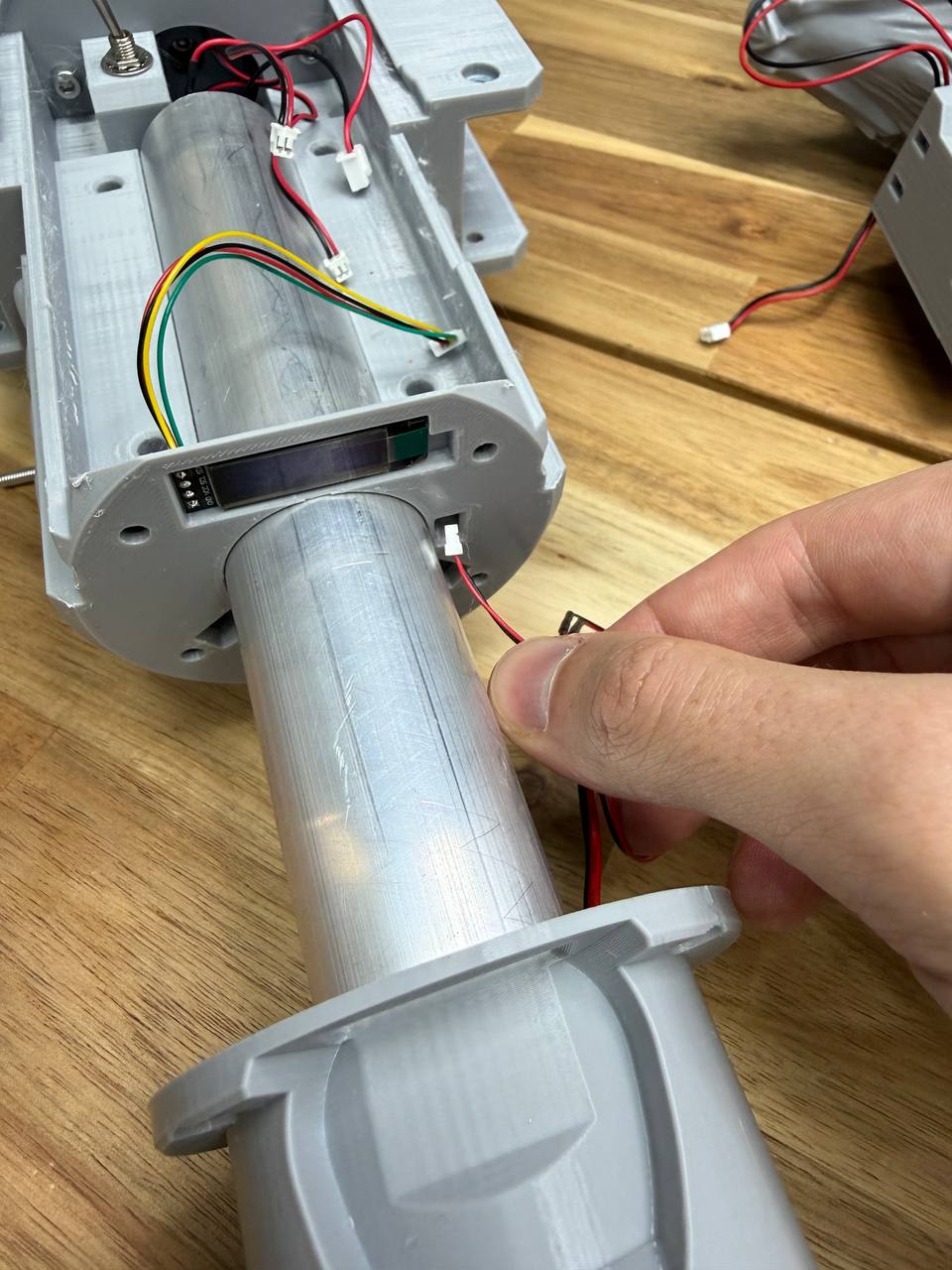
Thread the button wire from the handle through the cable channel inside the main body. Pull the wire out through the small window at the end of the body — use tweezers or your fingers to grab the wire end. Then push the tube with the handle all the way in.
08 Secure the handle
Fasten the handle to the body with four M4x20 screws around the handle flange, as shown in the photo.
09 Prepare the tube brackets
10 Install the tube brackets
Place the brackets onto the tube with the nut holes facing toward the speaker housing. Secure the brackets with M5x20 screws. Tighten the screws gradually, alternating between left and right — a little on the left, a little on the right, back to the left, back to the right. Do not fully tighten one side first, as this will cause the brackets to sit unevenly.
Blade Assembly
01 Install the blade
Thread the motor wire through the main body so it comes out the other side. Seat the blade into the body and secure it with four M4x20 screws — two on each side.
01 Install the blade
Insert the assembled chain elements into the blade guide, teeth facing outward. Push the chain forward until it reaches about halfway around the blade.
Then tilt the axe with the blade pointing downward at a slight angle to the horizon — this lets gravity pull the chain along the guide rails. Keep pushing until the chain comes out and advances along the lower part of the guide. Once it emerges, use your hand to pull it the rest of the way around to the bottom edge of the blade.
To close the chain loop, press it against the tensioner to create enough slack, then connect the two ends by snapping the chain links together. Press firmly on the link until it clicks into place.
ESP32 wiring
The old video guide also shows the assembly and wiring process for the ESP32—watch from the 22-minute mark. OLD VIDEO GUIDE
1 Install and solder the main boards
Place the ESP32, PAM8403 amplifier, PCM5102A DAC, TB6612FNG motor driver, and Mini560 voltage regulators into the board holder. Solder the main interconnection wires between these boards according to the wiring diagram. It is easier to solder the board-to-board connections before mounting the holder into the body.
Power distribution
You need two Mini560 step-down converters. Both take battery voltage (10–13V) as input and output 5V.
Mini560 #1 — powering the ESP32:
- IN+ → Battery positive (through switch)
- IN− → Battery negative (GND)
- OUT+ → ESP32 5V pin
- OUT− → ESP32 GND pin
Mini560 #2 — powering the amplifier:
- IN+ → Battery positive (through switch)
- IN− → Battery negative (GND)
- OUT+ → PAM8403 (HW-104) 5V pin
- OUT− → PAM8403 (HW-104) GND pin
Voltage divider for battery monitoring
The ESP32 cannot read battery voltage directly (10–13V would damage the GPIO pin). A voltage divider brings it down to a safe level.
- Battery positive → 10K resistor → junction point → 2K resistor → GND
- Junction point (between the two resistors) → ESP32 analog input pin
The Mini560 voltage regulator has IN+ and IN− terminals — connect:
- IN− → 2K resistor
- IN+ → 10K resistor
Motor driver — TB6612FNG
The TB6612FNG controls motor speed and direction.
| TB6612FNG Pin | Connect To |
|---|---|
| VM | Battery positive (motor power, 10–13V) |
| VCC | STBY |
| GND | Common GND |
| PWMA | ESP32 GPIO pin18 |
| AIN1 | ESP32 GPIO pin16 |
| AIN2 | ESP32 GPIO pin17 |
| AO1 | Motor terminal 1 (do it latter after install board holder in palce) |
| AO2 | Motor terminal 2 (do it latter after install board holder in palce) |
| STBY | mini 560 OUT+ |
Audio — PCM5102A DAC to ESP32
The PCM5102A receives digital audio from the ESP32 via I2S protocol.
| PCM5102A Pin | Connect To |
|---|---|
| BCK | ESP32 PIN 6 |
| DIN | ESP32 PIN 5 |
| LRCK (LCK) | ESP32 PIN 4 |
| GND | Common GND |
| VIN | ESP32 3.3V |
Audio — PCM5102A DAC to amplifier (PAM8403 / HW-104)
The analog audio output from the PCM5102A goes to the amplifier.
| PCM5102A Pin | PAM8403 (HW-104) Pin |
|---|---|
| LROUT | L (left input) |
| AGND | G (ground input) |
| ROUT | R (right input) |
Volume control — A103 10K dual potentiometer
There’s no difference between left and right here. The important thing is that the outer pins are connected—one to 3V, the other to ground—and the middle pin goes to ESP32 output pin 2.
| A103 | ESP32 |
|---|---|
| left pin | 3v3 |
| middle pin | pin 2 |
| right pin | gnd |
OLED display — SSD1306 128×64 I2C
| OLED Pin | Connect To |
|---|---|
| GND | Common GND |
| VCC | ESP32 3.3V |
| SCL (SCK) | ESP32 SCL pin38 |
| SDA | ESP32 SDA pin39 |
2 Route external cables through the board holder
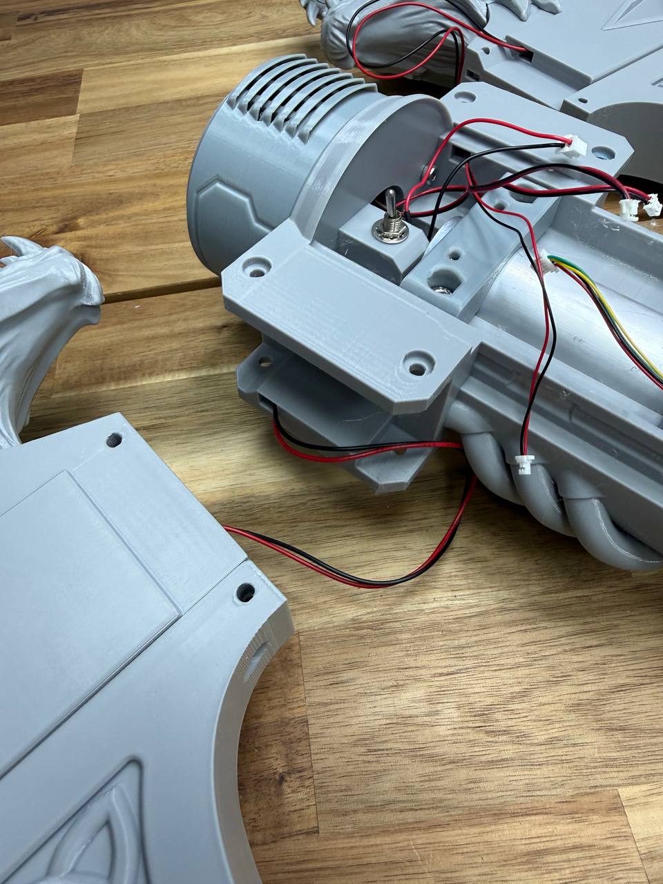
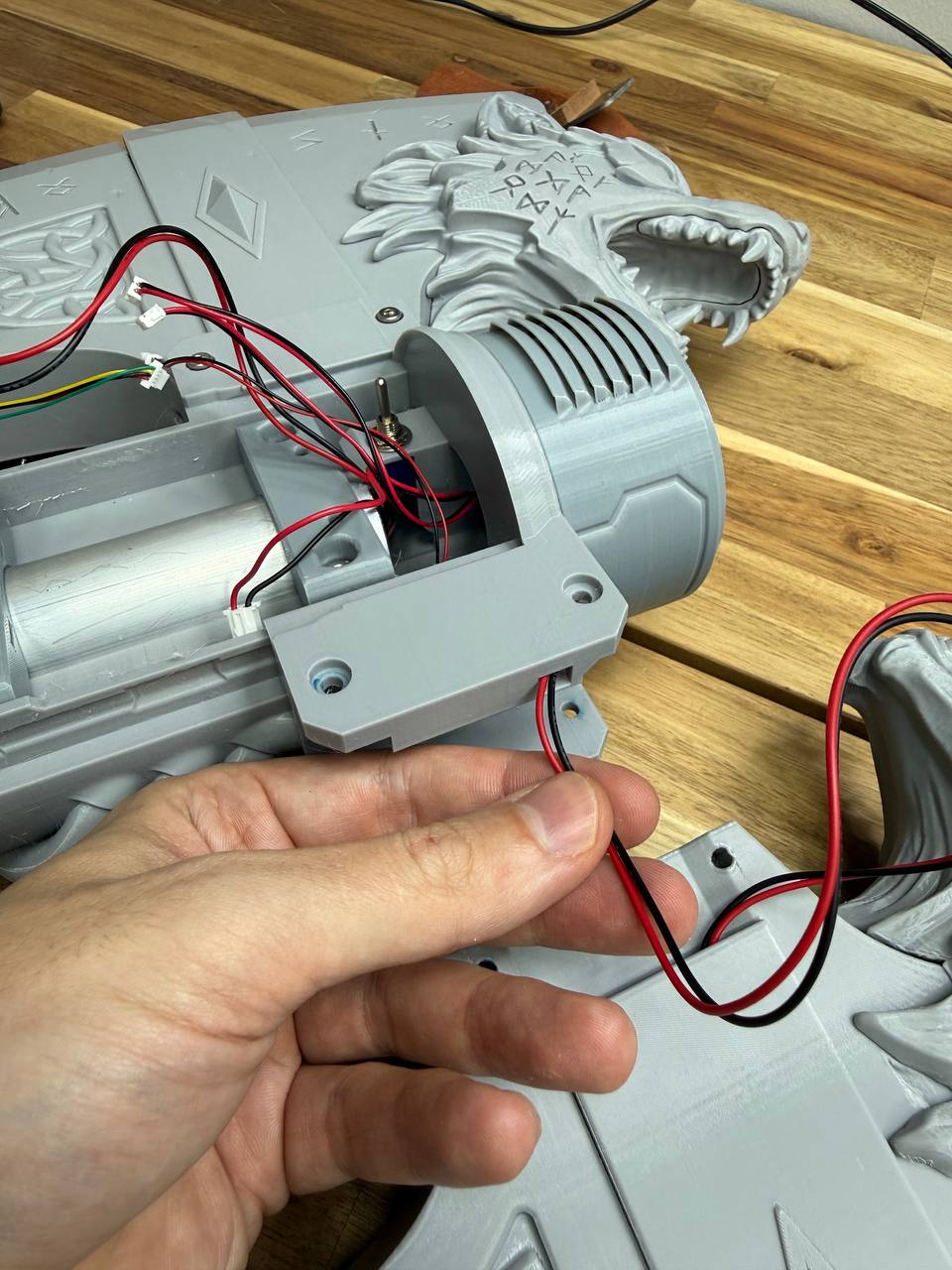
Before securing the board holder, thread the following cables through it: motor wires, trigger button wires, speaker wires, and the main power cable.
Secure the board holder
Fasten the board holder to the bracket with four M3×16 screws.
Solder the remaining connections
Solder the remaining wires to their designated contacts on the boards according to the wiring diagram: display cable, trigger button wires, power cable, and speaker wires.
Trigger buttons
- One leg → ESP32 GPIO pin 40
- Other leg → GND
Polarity doesn’t matter here either—connect one wire (any color) to pin 40 and the other to ground.
Amplifier to speakers
The PAM8403 (HW-104) has left and right output terminals. The speakers are 40mm 5W 4Ω
- Speaker 1 positive → HW-104 L OUT+
- Speaker 1 negative → Speaker 2 positive (jumper wire, ~5 cm)
- Speaker 2 negative → HW-104 L OUT−
Use approximately 20 cm of wire for speaker connections.
**ESP32-S3 firmware**
Text after title text example
The board firmware is shown in more detail in the video. Watch from the 30-minute mark.
Download the program for flashing esp boards and unzip the archive https://www.espressif.com/en/support/download/other-tools
Download firmware files
When you launch the program, select ESP32 S3. Plug the USB cable into the board, in the COM port window, select the required port (if you don’t know which one, unplug the cable, check the list of available ports, plug the cable in again, another available port will appear that wasn’t available before, and that’s what you need)
There are only 4 files in the firmware, each file is in a separate folder, the folder name must be copied and pasted into the window opposite the specified path to the firmware file and so on for all 4 files. put a tick on
Basic operation
01 Insert batteries and power on
Take three standard AA battery holders. Insert the batteries with the negative (−) end on the spring and the positive (+) end on the flat contact — the same way you would insert batteries into any device. Assemble three holders with three batteries each.
Insert the battery holders into the battery compartment as shown in the photo, with the spring (positive) side facing toward the positive (+) contact of the compartment. Insert all three, then slide the battery compartment into the handle and secure the end cap.
Painting
This section is currently under development. A more detailed painting guide may be added in the future. Below are the key points to keep in mind when painting your axe.
⚠ Important — protect moving parts
Do not apply primer or paint to the chain, chain guides, or any moving surfaces. Paint is a sticky substance — if it gets on the guide rails, the chain will stick or rotate poorly due to increased friction between the links. This can lead to motor overheating and potential electronics failure.
Before painting, cover all internal surfaces and guide rails with masking tape. If paint accidentally gets on the guides or chain, make sure to thoroughly clean it off. The chain must rotate freely and slide along the guides without resistance.
Painting the chain
Paint the chain elements either separately before installation, or very carefully while installed — making sure that primer and paint do not get inside the links where they slide against each other.
Surface preparation
Sand the plastic surface before painting to improve adhesion. You can then apply a filler primer or automotive putty to smooth out layer lines.
An excellent alternative for smoothing print layers is UV resin. Apply a thin coat of photopolymer resin to the surface, then gently heat it with a heat gun or torch to remove air bubbles. Cure it under a UV lamp. Sand away any drips or uneven spots, then apply primer followed by paint.
Paint options
You can use acrylic craft paints or automotive spray paints. I typically use FolkArt acrylic paints — they come in larger bottles compared to modeling paints, making them a good option in terms of both price and quality. Spray cans also work well, especially for base coats and large surfaces.
Always apply primer before painting, regardless of which paint type you choose.